(508) 226-3350
|
Products & Services
Custom Components Resistors Terminations Attenuators QFN Packages QFN Assembly Partner |
Sales USA Sales Reps International Sales Reps Distributors RFQ Online Warranty |
About Us Vertical Integration Corporate Overview ISO9001:2015 Job Opportunities Privacy Policy |
 Download Brochure |
|||
|
Copyright © 2025 Vishay Barry - Sfernice Division
|
||||||
Terminations for Pulsed Power
T Series 'E' Type
T Series 'E' Type
Pulsed power applications present a unique set of thermal problems. Frequent cycling of power can cause materials to expand rapidly, sometimes with destructive effects.
By closely matching the Coefficient of Thermal Expansion (CTE) of adjoining materials, catastophic failures can be eliminated.
By closely matching the Coefficient of Thermal Expansion (CTE) of adjoining materials, catastophic failures can be eliminated.
Click on link for available Data Sheet. For more options, please contact us with your requirement.
(Click on column header to sort)
(Click on column header to sort)
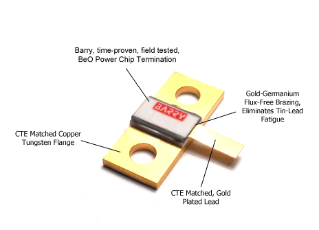
To minimize CTE mismatch and increase thermal conductivity, a Gold-Germanium eutectic is used to bond the BeO to the flange. To further minimize CTE mismatch, a Copper-Tungsten flange is used.
The Gold-Germanium layer is chemically compatible with the Gold plated ajoining layers, and no embittling metallics will form. The Gold matrix exhibits outstanding ductility, corrosion resistance, low diffusivity and low toxicity, as opposed to lead.
Below are Barry Industries' Copper Tungsten flanged terminations. Engineers are welcome to contact us and we will design a Copper Tungsten flanged termination to your exact specifications.
Specifications:
Resistive Element:
Substrate:
Mounting Flange
Leads:
Resistive Element:
Substrate:
Mounting Flange
Leads:
Proprietary Thick Film
BeO
Copper Tungsten
Gold Plated Copper (.005" thick)
BeO
Copper Tungsten
Gold Plated Copper (.005" thick)
Cycling Test Details
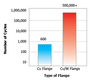
• Applied Power: 250W
• Cycle: 10 seconds On, 10 seconds Off
Cycling Test Results
• All Copper flanged resistors failed after 600 cycles
• All Copper-Tungsten flanged resistors still operational after 500,000 cycles
• Applied Power: 250W
• Cycle: 10 seconds On, 10 seconds Off
Cycling Test Results
• All Copper flanged resistors failed after 600 cycles
• All Copper-Tungsten flanged resistors still operational after 500,000 cycles


Below are some of Barry Industries' Standard High Power Flanged Resistors. Engineers are welcome to contact us and we will design a Custom High Power Flanged Resistor to your exact specifications.
Customer defined testing is available for all Barry devices.
Customer defined testing is available for all Barry devices.
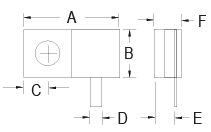
Left Configuration
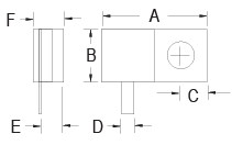
Right Configuration
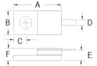
Center Configuration
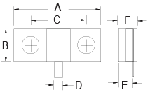
2 Hole Configuration
For more information regarding the benefits of using Copper-Tungsten flanged resistors high thermal cycle environments click here

